Providing optical design and development.
Precision injection molding by ultra-precision tooling and mold.
Customized design.
General LED retrofit spotlights include MR16, GU10, PAR, and R lamps. These LED spotlights mimic traditional halogen lamps. According to the categorization of LED retrofit lamps by ENERGY STAR in the United States, the classification is shown in Table 1 below. Retrofit spotlights fall under the "directional" light lamp category, and the mentioned MR16 and PAR lamps belong to the MR and PAR categories within this classification.
| Table 1. ENERGY STAR Classification of LED Lamps | |||
| Omnidirectional | Decorative | Directional | Non-standard |
| A, BT, P, PS, S, T。 | B, BA, C, CA, DC, F, G | BR, ER, K, MR, PAR, R | N.A. |
ENERGY STAR, one important indicator of early LED lamps development, has guided the LED lighting industry in developing practices that can directly replace traditional light lamp, which is referred to as “retrofit”. A retrofit lamp means one can directly install LED lamps into the sockets of traditional light lamp. It is the initial stage of replacing the traditional lighting with LED retrofit lamps.
MR stands for Multifaceted Reflector. The number of MR represents the diameter of the lamp's opening. A number 8 means 1 inch. Take MR16 for example, the number is 16. The 16 divided by 8 equals 2. This means that the diameter of lamp's opening for MR16 is 2 inches, which is approximately 5.08 cm (2 x 2.54 cm = 5.08 cm). The figure below shows the traditional shape of a halogen lamp, which has multiple facet patterns. This facet pattern is commonly referred to as a "multifaceted."
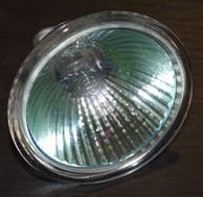 Figure 1. Traditional MR16
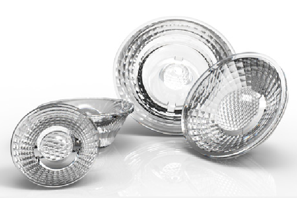
The emitter of MR16 has changed from halogen to LED during a decade, the design structure of MR16 has been also changed. The traditional multifaceted structure was replaced with TIR (Total Internal Reflection) lens depicted in the figure 2. TIR lens technique can make LED MR16 achieve lighting effects equivalent to traditional halogen MR16 lamps, which is recommended by ENERGY STAR. TIR lens techniques rapidly developed after 2010 and have become very mature. There are various optics design methods proposed to replace traditional halogen MR16 lamps.
Figure 2. TIR lens with multifaceted
How to apply multifaceted patterns on a TIR lens becomes popular as the development of TIR lens is mature. The diversifications of multifaceted patterns and the thin TIR-R lenses became coral studies for various optical manufacturers around 2012. Multifaceted technology is a power tool for industrial design of lighting fixtures. Our company specifically focuses on the development of basic algorithms for building various multifaceted patterns on arbitrary smooth surface, which are further explained on the "Multifaceted Patterns Technology" page of our website.
The bases of MR16 lamp are mainly divided into GU 5.3 and GU 10 shown separately in figure 3 and 4. The "G" represents a lamp base that is directly inserted, and the "U" indicates that the base (including pins) has a U-shaped appearance. The number (following "U") represents the center distance between the pair of pins. Due to differences in sockets, MR16 is often referred to as GU 10 as well.
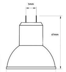 Figure 3. GU 5.3 base of MR16
|
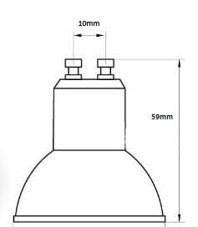 Figure 4. GU 10 base of MR16
|
PAR stands for Parabolic Aluminized Reflector, which means a reflector with a parabolic shape coated with aluminum, as shown in the figure 5. Aluminum is coated on the reflector's surface where light is effectively reflected towards the end, marked E in figure 5. The number following PAR represents the opening diameter. For example, in the case of PAR 20, when divided by 8, it equals 2.5. This means the opening diameter for PAR20 is 2.5 inches, which converts to approximately 6.35 cm (2.5 x 2.54 cm = 6.35 cm). Thus, the opening diameter for PAR20 is approximately 6.35 cm (often marked as 65 mm).
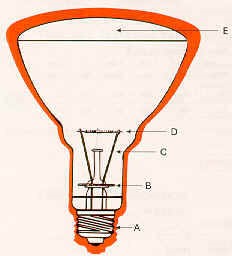 Figure 5. Traditional PAR Lamp
The general sizes of PAR lamps are summarized in Table 2 below. In the market, the most common are PAR16, PAR30, and PAR38, with corresponding opening diameters found in the table 2. Like MR16, the structure of the traditional lamp doesn’t have a reflective surface. It has been replaced by TIR lenses as the secondary optical element to adjust the directions of light , as shown in the example of a PAR30 using TIR lens in the figure 6 below.
| Table 2. Opening Diameter of General PAR Lamp | ||
| Diameter
(inch) |
Diameter (mm) |
|
| PAR64 | 8 | 200 |
| PAR56 | 7 | 175 |
| PAR46 | 5.75 | 145 |
| PAR38 | 4.75 | 120 |
| PAR36 | 4.5 | 115 |
| PAR30 | 3.75 | 95 |
| PAR20 | 2.5 | 65 |
| PAR16 | 2 | 50 |
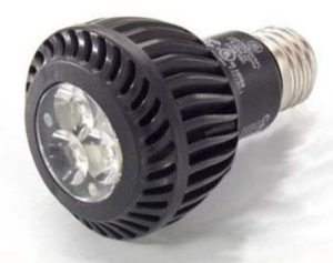
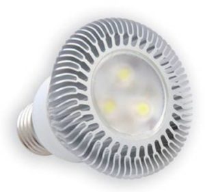 Figure 6. LED PAR30 lamp
About the PAR lamp base, because it's a retrofit lamp, the socket remains the same and is compatible with traditional PAR lamps which use an Edison screw shown in figure 7. In the designation "Exx", "E" stands for "Edison" and "xx" indicates the diameter in millimeters as measured across the peaks of the thread on the base, e.g., E12 has a diameter of 12 mm. Some examples include E14, E16, E27, and E40.
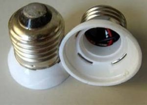 Figure 7. Edison screw of LED PAR30 lamp
| Table 3. GE PAR Appearance and Specification | |
 GE PAR20 Lamp
 |
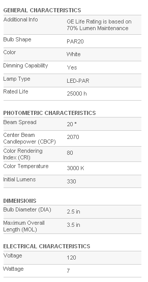 GE PAR20 spec
 |
In Table 3's specification descriptions, there are two optical indicators related to the TIR lens, which are Beam Spread (Beam Angle) and Center Beam Candlepower (CBCP). Beam angle and CBCP are specs used by lighting or lamp designers to plan and layout. They are also served as a measure of the lamp's equivalent lighting capability of replacing traditional ones, as suggested by ENERGY STAR. A more detailed explanations of ENERGY STAR's lighting-related specifications will be provided on another page in this web.
Describing the distribution of light in space is a complex task. In LED industry, the Full Width at Half Maximum (FWHM) is a common way to describe the intensity distribution of light. FWHM represents the difference between the two values of the independent variable at which the dependent variable is equal to half of its maximum value, which is shown in figure 8.
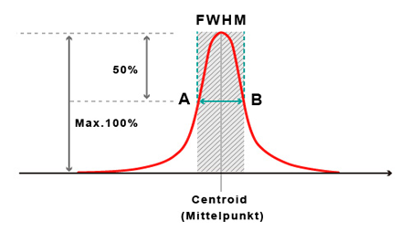 Figure 8. FWHM
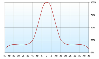
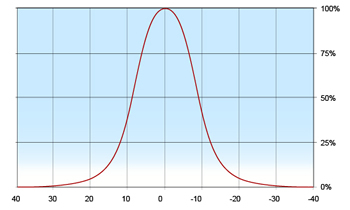
The advantage of FWHM is that it provides a single numerical value to roughly describe the spatial distribution of light. For example, FWHM values of 120° and 30° represent different light distribution patterns, as listed in the table 4.
| Table 4. The illustrations of FWHM 120 and 30 degrees | |
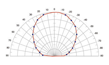 FWHM 120 degree
 |
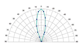 FWHM 30 degree
 |
In the LED industry, FWHM has been used for decades, it is a very important and useful index for describing the intensity distribution of LEDs. However, in recent years, as LED lighting has gained popularity, using FWHM alone as a lighting indicator has proven insufficient. For instance, one can see the red and blue lines in the figure 9, which both they represent FWHM values of 10°. Although the FWHM values are the same, the light patterns are much different.
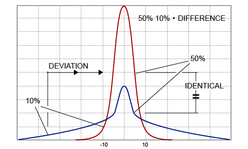 Figure 9. Same FWHM but different view angle
Simply using FWHM as the indicator to describe light distribution in space has limitations in practical lighting applications. To address this, a new approach that considers both the FWHM and the View Angle has emerged. The View Angle means that the range of intensity distribution defined as the position where 10% of the maximum intensity is. By combining FWHM and View Angle, one can avoid the misunderstanding shown in figure 9. We can regard the red line as 10°@20° and blue one is 10°@70°. The first number is FWHM, and the last number is View Angle. It is stark difference between the light distribution patterns.
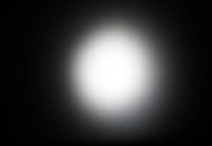
The View Angle index used in lighting is to describe the degree of halo. When the difference between the View Angle and FWHM is very small, which means that the halo is very slight (cutoff is good). While the difference is very large, which means that the halo is very wide (cutoff is poor). The effects of lighting patterns are obvious shown in the table 5, when the patterns of View Angle are difference.
| Table 5. Illustrations of the cutoff with FWHM@View angle | |
 FWHM 20° – View angle 90°
 |
 FWHM 18° – View angle 40°
 |
 light pattern 20_90
 |
 light pattern 18_40
 |
FWHM's other name is referred to as the Beam Angle, and it is commonly used in LED component specifications. It has the same definition as FWHM, but it is often used as a single value to describe LED light distribution, assuming rotational symmetry. For elliptical light patterns, two Beam Angle values will be used to describe the distribution.
High-speed CNC machines are currently the mainstream in the non-imaging optics industry, coupled with three-axis, four-axis, or five-axis CNC machining depending on the lens design. For instance, for lenses with rotational symmetry, a three-axis CNC with a speed of 30,000 RPM is sufficient. However, for non-symmetrical freeform designs or high surface smoothness requirements, a four-axis or five-axis CNC with a speed of 60,000 RPM is recommended to achieve excellent surface shape and finish.
No. 53, Yuanbai Road, Economic and Technological Development Zone, Longquanyi District, Chengdu City, Sichuan Province
TEL:15198055548
FAX:+86-28-84851939