Providing optical design and development.
Customized design.
A typical application of the LED with secondary optical lens is shown in the Figure 1. The theoretical loss on the perfect surface of TIR (Total Internal Reflection) should be close to zero. However, in practice, due to manufacturing process, the optical surfaces cannot be perfectly smooth, resulting in some inevitable losses. In the Figure 1, if we consider the light energy emitted from the exit surface of the TIR lens as the active lumen output, then the overall light efficiency of the optical system can be represented as: active lumen / lumen from LED.
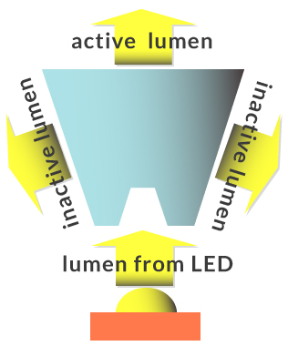 Figure 1. A typical illustration of using LED with secondary optical lens.
At the initial design phase, one can estimate the reasonable luminous flux emitted from LEDs by the datasheet of LED and relevant thermal effect:
1. Initial lumen:
It means that the temperature of the LED is close to the ambient temperature (usually 25 degrees Celsius). When the LED is lit up, one instantly measures the lumen, it is so-called initial lumen or cold lumen.
2. Steady state lumen:
One measures the lumen emitted from LED that is continuously driven at a fixed current for a period (typically 30 minutes or 1 hour). When the junction temperature (Tj) of the LED is stable, it is so-called steady state lumen or hot lumen.
Before estimating the reasonable lumen emitter from LED, we list the necessary information shown in Table 1 below. We take a Nichia 757, however, the same approach can be applied to LEDs from other manufacturers.
➢ LED model: The LED's product name for identification purposes.
➢ LED Sorting Current (Ifs): The reference current specified in the datasheet.
➢ LED Drive Current (Ifd): The actual current used when the LED is powered by the user.
Luminous Flux Bin: The upper and lower limits of a single luminous flux bin as specified in the datasheet.
➢ Luminous Flux Multiplier for Current (Mc): The multiplier determined by comparing the actual drive current to the Lm-If curve in the datasheet.
➢ Number of LEDs: Enter "1" for calculating the luminous flux of a single LED or the total number of LEDs for the entire luminaire.
➢ Factor of Thermal Impact (Ftm): The percentage of luminous flux reduction due to the Tj of LED.
➢ Factor of Optical Impact (Fopt): The percentage of luminous flux reduction caused by the secondary optical components.
| Table 1. Information for LED Luminous Flux Calculation | |||
| LED Model | Nichia 757 | ||
| LED Sorting Current | 0.15 | A | |
| LED Drive Current | 0.18 | A | |
| Luminous Flux Bin | Min | Typ. | Max |
| 70 | 80 | 90 | |
| Luminous Flux Multiplier for Current | 1.2 | ||
| Number of LEDs | 1 | ||
| Factor of Thermal Impact | 0.9 | ||
| Factor of Optical Impact | 0.8 | ||
Note: Nichia is a well-known Japanese LED brand company.
To calculate the LED's luminous flux reasonably, the first step in the calculation is to start from the "base value." It is recommended in this article to use values explicitly stated in the specification sheet as the base value, as shown in the figure below.
 Figure 2. Specification values from model 757*
*The specification values of Nichia's 757 LED mentioned in this article are taken from Nichia's 757 specification datasheet.
In the above figure, the relevant specification values from Nichia's specification datasheet are explained item by item as follows:
①:Ts value shows 25°C , indicating that the listed specification values are obtained at an LED junction temperature of 25°C.
②、③:When the LED is rated at If = 100 mA and Ts is 25 degrees, the luminous flux emitted by the LED is 70 lumens.
④:The value represented here indicates the official recommended standard value (typ.) of the LED. A more rigorous approach would involve looking up the min and max values from the luminous flux bin table. However, different companies in the industry have different binning rules. If it's challenging to find the formal binning rules in the specification datasheet, it is recommended to roughly estimate the min and max luminous flux by approximately ±5% deviation, as shown in the table below.
| Table 2. Example of Luminous Flux Range for a Single LED Bin | |||
| Lumen range | min | typ. | max |
| Lumen | 66.5 | 70 | 73.5 |
Next, the second step is to calculate the luminous multiplier based on the LED's operating current. For example, if the LED is being driven at 150 mA. First, refer to the "Current vs. Luminous Flux" curve chart in the datasheet, as shown below:
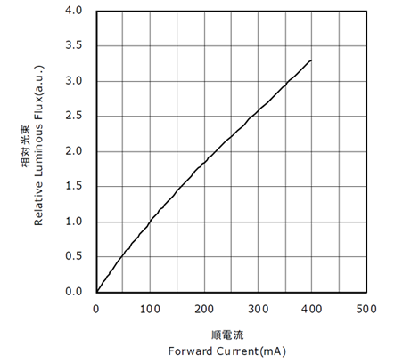 Figure 3. Lm-If curve chart of Nichia’s 757 LED model
| Table 3. Luminous Values at LED Driving Currents | |||
| Luminous Flux Multiplier for Current | 1.4 | ||
 Figure 4. lm-Tj curve from the datasheet of Nichia's 757 LED model
| Table 4. Luminous flux multiplier value affected by Tj of LED | |||
| Factor of Thermal Impact | 0.86 | ||
A customer uses Luxeon Z ES LEDs with a driving current of 800 mA. According to the result of the customer's thermal design, the measured Ts temperature is 105°C, and the LED's color temperature is 2700K. We want to know:
①What is the estimated LED output luminous flux?
②What is the luminous flux after passing through the lens (with lens efficiency of 0.86)?
First, obtain the relevant specification values from the LED's datasheet, as shown below. Since the used LED with a color temperature of 2700K. We extracted the values for 2700K shown in figure 5. Please note that Luxeon Z ES's specification values are measured at Tj=85°C, which is different from the 25°C reference of Nichia used previously.
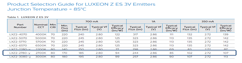 Figure 5. Partial extraction of specifications from the datasheet from Luxeon Z ES LED Model*
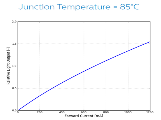 Figure 6. The Lm-If curve of Lumileds' Luxeon Z ES LED Mode
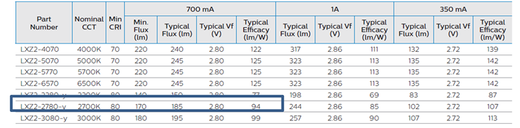 Figure 7. Partial extraction of lumen values for various color temperatures of Luxeon Z ES
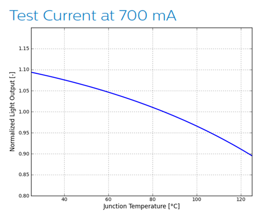 Figure 8. The Lm-Tj curve of Luxeon Z ES Model LED
| Table 5. Calculations for LED luminous flux | ||||||||||
| Range | Ifs | Ifd | Base Lm | Mc | LED No. | Initial Lm | Ftm | Hot Lm | Fopt | System Lm |
| min | 0.7A | 0.8A | 185.3 | 1.15 | 1 | 213.09 | 0.853 | 181.77 | 1 | 181.77 |
| typ. | 0.7A | 0.8A | 201.65 | 1.15 | 1 | 231.89 | 0.853 | 197.80 | 1 | 197.80 |
| max | 0.7A | 0.8A | 211.73 | 1.15 | 1 | 243.48 | 0.853 | 207.69 | 1 | 207.69 |
| Table 6. Calculations for LED luminous flux with Fopt | ||||||||||
| Range | Ifs | Ifd | Base Lm | Mc | LED No. | Initial Lm | Ftm | Hot Lm | Fopt | System Lm |
| min | 0.7A | 0.8A | 185.3 | 1.15 | 1 | 213.09 | 0.853 | 181.77 | 0.86 | 156.32 |
| typ. | 0.7A | 0.8A | 201.65 | 1.15 | 1 | 231.89 | 0.853 | 197.80 | 0.86 | 170.10 |
| max | 0.7A | 0.8A | 211.73 | 1.15 | 1 | 243.48 | 0.853 | 207.69 | 0.86 | 178.61 |
No. 53, Yuanbai Road, Economic and Technological Development Zone, Longquanyi District, Chengdu City, Sichuan Province
TEL:15198055548
FAX:+86-28-84851939