Providing optical design and development.
Customized design.

In the field of non-imaging optics, particularly in LED lighting design, it is often necessary to choose far-filed or near-filed method to build the simulation model. The choice will determine the simulation setting for non-imaging optical lens design and development. Especially for near-field applications, the optical results between simulation and actual products will differ significantly. The concepts of far-field and near-field do not have very clear definitions in current scientific literatures. To understand these concepts, take star as example, a star has diameter of up to a million kilometers. The size of star is much large. However, if one views the star from a far, far away location, the star seems to be a point source. The scene is like a person see stars in the night sky. These are depicted in the diagram below.
 |
 |
| Figure 1: Illustration of Near-Field and Far-Field due of the distance | |
Extending this concept to non-imaging optical design, especially lens design, in most applications, there will be emitters and lenses used in a non-imaging optical simulation model. When the optical lens is close to the emitter, and the size of lens is equivalent to the size of emitter, the near-field characteristics will be obvious (the emitter can’t be treated as a point source). Conversely, when the optical lens is far from the emitter, and the lens size is much larger than the emitter, far-field characteristics will be obvious (the emitter can be treated as a point source).
Currently, there are no well-defined theoretical formulas or calculations for defining near-field and far-field in the academic or industry. Based on extensive experience, engineers have roughly determined that when the distance and size of the lens exceed 15 times the size of the emitter, it is appropriate to consider it a far-field application. When the values are below 15 times, it becomes essential to carefully set and verify the optical simulation model, one shall check the differences between optical simulation and practical measurement.
As optical components are much close to emitters, the near-field characteristics will be obvious. Take designing a secondary TIR lens for LED spot fixtures, it is better to use a measured ray-file in the optical simulation. This method has been recognized as a relatively accurate way of emitter modeling in the past decade.
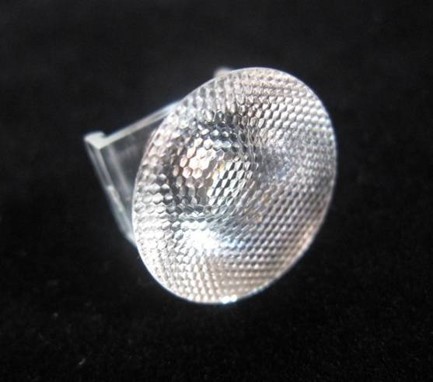
Figure 2 provides an illustration of a TIR lens with Fly-eye microstructures. Fly-eye is a microstructure arrangement frequently used in traditional glass products. It widely employes microstructure arrangement of the exit surface of glass, such as frosted glass. When applying to TIR lenses, the exit surface with Fly-eye microstructures makes the light pattern be more uniform, it also can change the shape of the light pattern. This theoretical concept is called “convolution”, which means that rays of the emitters are converged to be a small angle. As different fly-eye is used, the different light pattern will be created. Hexagonal arrangement is commonly used in TIR lenses for LED lighting, as shown on the left in Figure 2.
During the period from 2007 to 2009, when LED lighting was in its early stages. The lumens per watt were not very high, and high-power LEDs were very expensive. How to implement precise TIR lens designing and manufacturing was a centerpiece of no-imaging optics. Many engineers in this industry were initially unaware that the size and distance of TIR lenses were already within the near-field range. At that time, there was very little practical experience with near-field optics. Many believed that using spatial apodization or point source method could obtain accurate optical simulation results. However, it is wrong. When engineers were aware of the near-field characteristics, they switched to used measured ray-file to build emitter model. After 2014, TIR lens design became a mature non-imaging optical technology product and had a 10-year period of prosperity.
 |
 |
| Figure 2: Example of Near-Field Optics Application - TIR Lens with Fly-eye Microstructures | |
For more discussions on the precision of LED emitter modeling, one can refer to the Analysis of a LED Emitter in Optical Simulation page on this website.
A good example of far-field optics application can be illustrated by using Dialux, a highly renowned lighting fixtures layout software. Dialux is a powerful layout and analysis software that is available for free download. It offers various features for lighting design including indoor, outdoor, sports, street, and other special applications. Dialux is free for users. Luminaire manufacturers pay the fee to the software company to put their IES files* in the luminaire library of Dialux. The IES files which is a kind of format of spatial apodization are measured from the luminaire products. One can import an IES file into Dialux to present as a luminaire. However, in Dialux, any imported luminaire is considered be far-field, so the geometric size of the luminare itself does not affect the far-field results.
*Dialux supports various file formats. The IES or LDT is popular format commonly used in lighting industry. These files can be converted by simulation software into light intensity distribution emitter.
Figure 3 demonstrates the analysis result of light distribution of a luminaire after importing an IES-format file into Dialux. This light intensity distribution is equivalent to the illumination of the luminaire light source considered as a dummy point source without geometrical size in the software. In Dialux, designers can freely arrange these light sources - similar to arranging luminaires - according to their needs. For example, one uses Dialux to design the luminaire layout for a meeting room. The final illumination distribution is shown in figure 4.
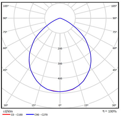 Figure 3: Example of importing luminaire light intensity distribution
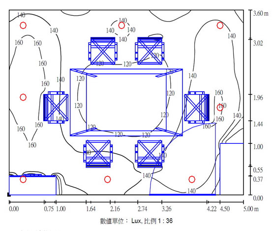 Figure 4: Example of illuminance distribution in a meeting room
After completing the entire lighting design, one can render the lighting design visualization within Dialux, as shown in Figure 5. This serves as a straightforward example of using the far-field concept for indoor lighting layout and application. For more details about Dialux, one can further visit the official Dialux website to obtain more detailed information.
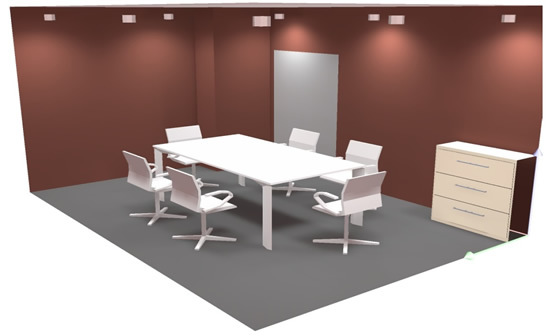 Figure 5: Rendering a 3D picture of the meeting room in Dialux
No. 53, Yuanbai Road, Economic and Technological Development Zone, Longquanyi District, Chengdu City, Sichuan Province
TEL:15198055548
FAX:+86-28-84851939